Cleaned, Inspected, and Greased Side Stand

Mileage: 29,424

Maintenance Summary:

  • Greased the side stand with moly grease.
  • Replaced missing 10mm nut (5/31/18)

The side stand is not as tight fitting as the center stand.  I don’t know if that’s the way it came from the factory, or it’s not tight because of a bit of wear.  The side stand is more heavily used, it’s under more stress (only one attachment point and heavy side stresses), and it’s probable that the stand hasn’t received regular maintenance.  That said, this simple design is very rugged and can take a lot of abuse.  While it might be possible to force some grease into the pivot bolt hole without removing the side stand, I chose to remove the side stand for a thorough cleaning and inspection.

To gain access to the side stand pivot bolt I dropped the entire exhaust system.  I did this by removing the header clamps, removing the bolts at both ends of the power box (three bolts total), and removing the two rider peg bolts.  This allowed the entire exhaust system to be lowered as shown here.
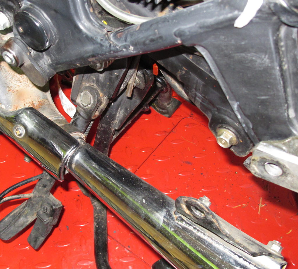
The side stand and pivot bolt were completely lacking in lubrication.  The stand is also missing a 10mm nut.  The stand is threaded so the missing nut is supposed to be there to lock the pivot bolt and keep it from spinning loose.  I’ll install the nut later.  (Update: Nut installed 5/31/18)

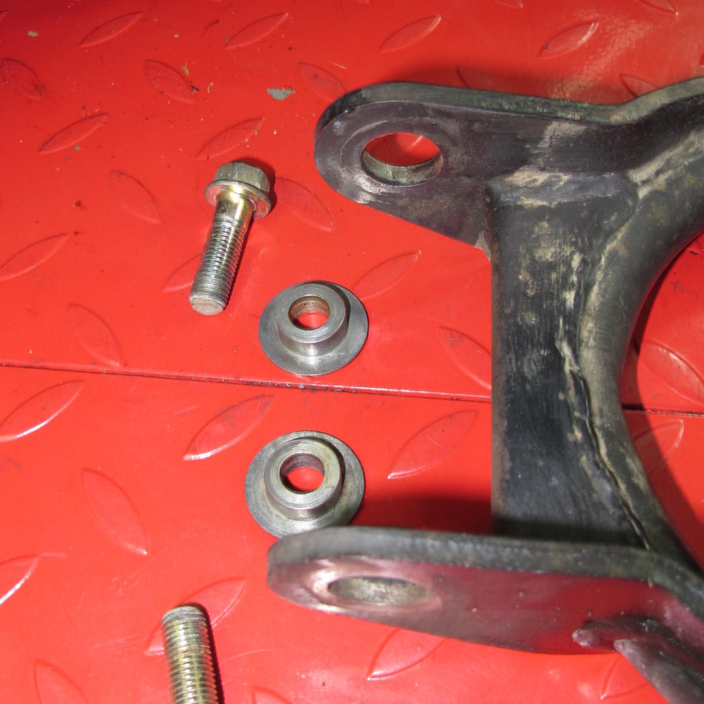
Below is the frame tab that the pivot bolt passes through.  The inner surfaces of the hole, the top of the tab on the outside, and the bottom of the tab on the inside is where most of the wear occurs.  If you enlarge the picture below you’ll see that the portion of the tab above the hole has wear not visible on the section below the hole.  You can also see the bit of bailing wire that I used to remove and reinstall the spring.
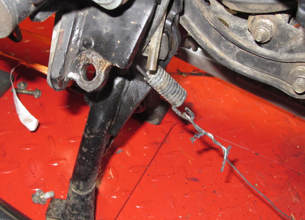
Hint:  Install the stand in the down position.  You won’t be able to lift the exhaust past the side stand if installed in the up position.  See the first picture to understand why. Install the spring after the exhaust system has been reinstalled.

Reinstalling the exhaust system was a bit of a pain and took some time.  The entire job took about an hour.

Installed new carb plugs and Misc. O-Rings

Mileage: 29,424

Maintenance Summary:

  • Installed new rubber plugs in carbs
  • Installed new o-rings in carb isolators
  • Installed new o-rings on both timing and crank adjustment caps

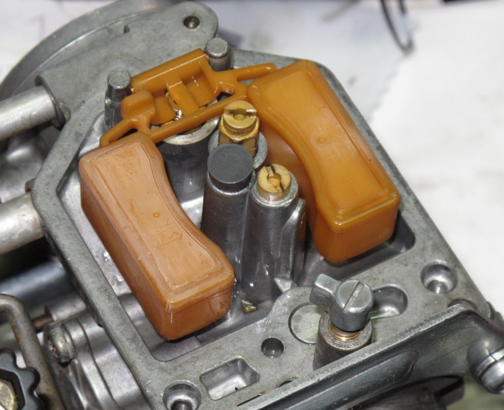
After re-installing the carbs which were removed to access the top rear shock pivot bolt, the bike seemed to be running very lean.  When I rebuilt the carbs  I didn’t replace the rubber plugs inside the bowls.   The plugs were in poor shape, and I was always worried that small pieces of rubber would find their way into a jet.

Having found some aftermarket plugs on eBay, it was time to pull the carbs — again.  Here one of the old plugs alongside the new.  Click on the picture to enlarge.The installed plug is near the center of this picture.  I did find one partially clogged jet.

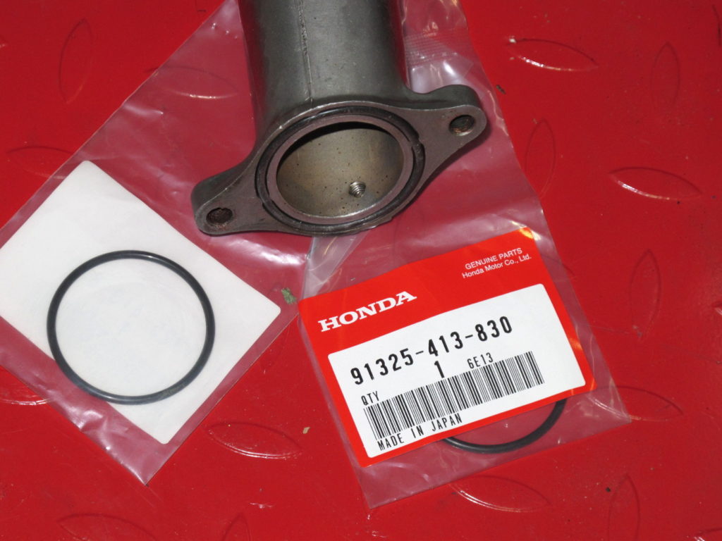
Another possible cause for the bike running lean is an air leak at the junction between the carb insulators and the cylinder heads.  I didn’t bother to test for a leak, I just replaced the o-rings at that junction when I re-installed the carbs.

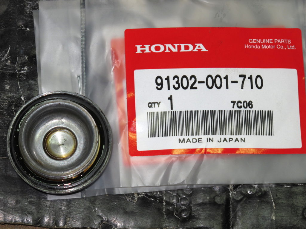
Two other o-rings that were replaced today seal the adjustment caps, or covers; the timing cover shown here always had a bit of oil around it.  There’s another identical cap between the clutch and the oil filter on the front of the engine.

The o-ring sits in a groove on the back side of the cap.  The new part seemed to be slightly undersized in terms of diameter.

After putting everything back together I took the bike for a short run.  It’s running great again!  The only problem that won’t go away is one where the temperature gauge sometimes doesn’t work.  I’m starting to suspect that the 7V regulator is intermittent.


Greased Center Stand and Rear Brake Pivot (shaft)

Mileage: 29,404

Maintenance Summary:

  • Greased center stand and rear brake pivot shaft with moly grease.

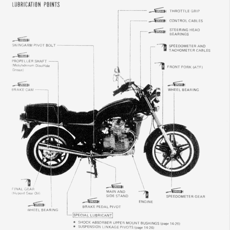
Often there are maintenance items that owners will ignore, even those who religiously perform other maintenance such as changing fluids.   While a poorly maintained center stand may not result in a crash, it can result in a more expensive repair after the miles start to pile up.  This diagram shows all of the various locations on the GL500 where lubrication is required.

Today’s task is to grease the center stand and the rear brake pedal pivot, which is a shaft that transfers the brake pedal motion from the right side of the bike to the left.

Unfortunately, the side stand bolt interferes with the exhaust system (power box), so I’m saving that maintenance task for another day.

As you can see in the next picture, the center stand pivots have not been lubricated in some time.  One of the reasons that people shy away from this task is the challenges of removing and re-installing the spring.  Honestly, it’s not that hard.  I used a breaker bar as a T-handle to pull on a bit of wire hooked over the end of the spring to both remove, and re-install the spring.  In the past I’ve also used vice grips.

I cleaned off the rust and corrosion using a wire brush, Scotch bright pad, and kerosene before greasing the moving parts and re-installing.  These parts support the entire weight of the bike when you’re putting it up on the center stand, more if you’re on the bike.  So they can wear if not well lubricated. Fortunately, while these haven’t been serviced in a while, the center stand doesn’t exhibit any wear.  It still feels tight.

Here’s a look at the underside of the bike with the center stand removed.  You can also see the side stand — which appears to be missing a lock nut.  Unfortunately the side-stand bolt can’t be removed with the exhaust in place.

The brake pivot was also greased.  All thats required to do this job is to remove the rear brake pedal from the right side and then slide the shaft out on the left side of the bike.  It will clear the frame.  I completely removed the shaft from the bike and then cleaned and greased it before re-installing.

As you can see, I removed the link rod going to the rear brake before pulling the pivot shaft.  The easiest way to do this is to first disconnect the link rod at the rear brake.  This allows the pivot rod to rotate making it easier to access and remove the cotter pin.

The pivot shaft isn’t under that much pressure, but it does have a lot of surface area.  Grease will ensure that the brake operation is smooth and that corrosion won’t cause binding.


Greased Rear Shock Upper Pivot Bolt

Mileage: 29,404

Maintenance Summary:

  • Cleaned and greased rear shock upper pivot bolt with high-moly grease.

When I recently serviced the rear suspension the one thing I didn’t do was service the top pivot bolt on the rear shock;  I couldn’t figure out how to get to it.   According to the service manual you can service the bolt without removing the air box.  Frankly, I couldn’t see how.

Look for the red arrow near the center of the picture below to find the bolt in question.  Here I’ve managed to get a socket on the bolt head using an socket extension and universal joint.  The extension passes through a narrow gap between the airbox and the frame.  Now, it might be possible to remove and re-install this bolt through this gap without removing the airbox (or carbs), but I don’t see how.

Note:  The nut on the left side of the shock is fixed in place making this job a bit easier.

The carbs are easy to remove on this bike, easier than the air box, so that’s what I did to gain easy access to this bolt.  The bolt was in very good shape with a little bit of old, very dry grease remaining.  I cleaned the bolt and coated it with high-moly grease before re-installing.

Note:  It’s a lot easier to remove and re-install this bolt with the rear wheel supported just enough to remove pressure from the bolt.  I used a block of wood and a large screwdriver under the tire.  When the bike is on the centerstand, the shock supports the rear wheel.

I have the seal required to rebuild the rear shock.  Those are no longer available from Honda, but I found a NOS part on eBay.  Since the shock is still holding air reasonably well I’ve decided not to attempt to rebuild the shock at this time.  Many people replace this shock with something else rather than rebuild them.

Fan, Tach Cable and Camshaft Seal

Mileage: 29,404

Maintenance Summary:

  • Replaced the following items:
    • Fan
    • Camshaft seal
    • Camshaft holder gasket
    • Camshaft holder o-ring
    • Tachometer cable and keeper screw.

While I had the front wheel off to rebuild the front forks, I decided to pull the radiator and fan so that I could replace the tachometer cable.  Well, as often is the case, once I had everything apart I found a few more items that required attention.

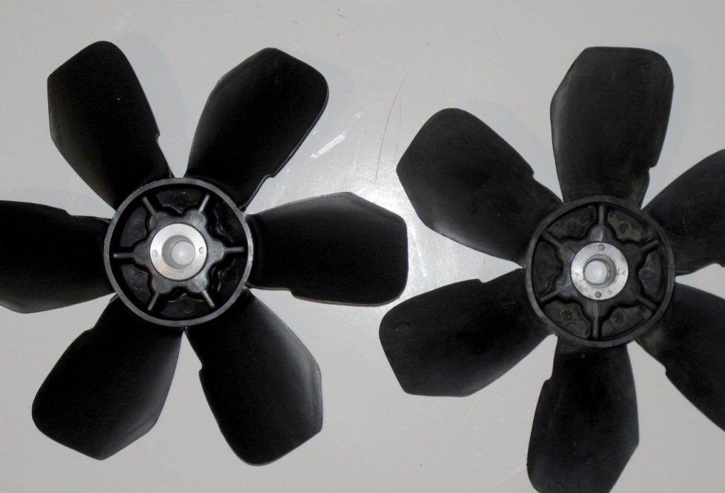
I pulled the fan using a 14mm bolt and the threads on the fan provided for this purpose.  It took a bit of work to get it to pop off the tapered shaft, but with a bit of pressure from the bolt and tapping on the end of the bolt with a hammer, it finally gave way.   The first thing I looked for was cracks in the fan — a common problem on this bike.   Sure enough, every rib has radial cracks extending from the aluminum hub.

Left unchecked a cracked fan has the potential to fail catastrophically and damage the radiator.  After briefly considering converting the bike to an electric fan, I decided to keep the bike original.  These fans are still available from Honda, and relatively affordable at $30.  Thank you Honda! I probably would have switched to an electric fan if the conversion didn’t require cutting off the end of the camshaft, or the fan was no longer available.

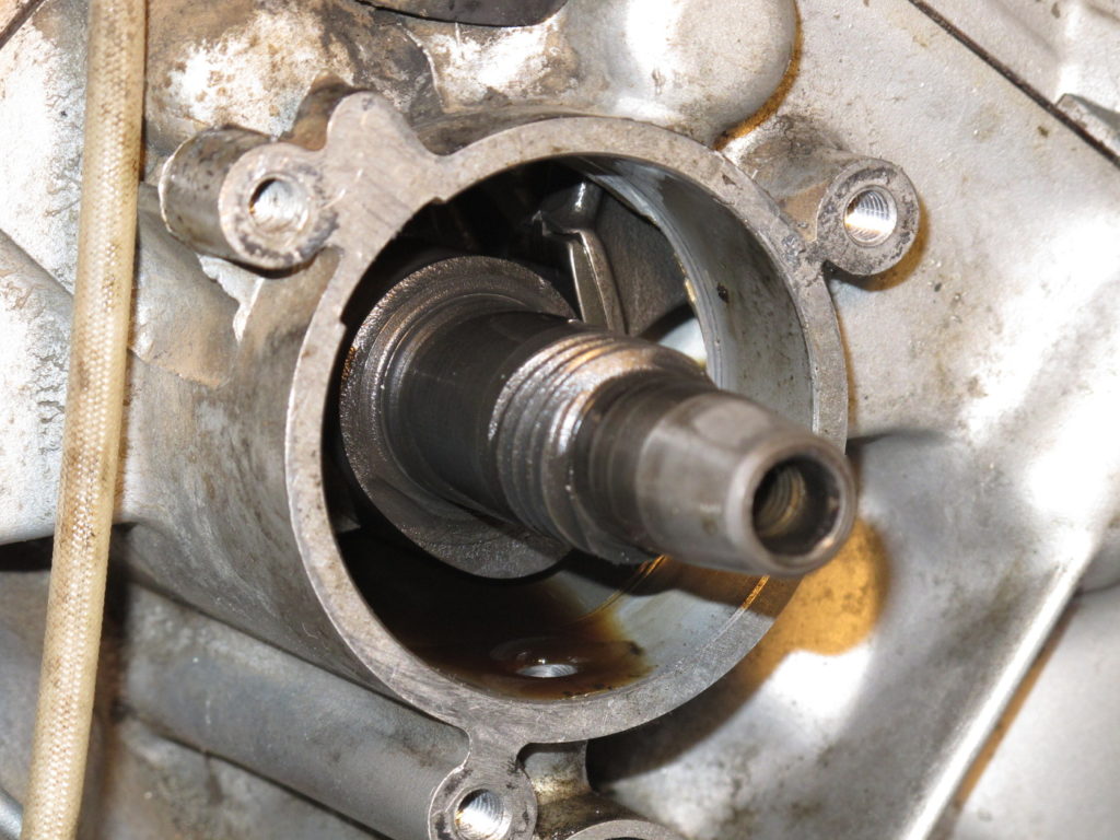
The cracked fan isn’t the only problem I discovered.  As you can see in the next photo, the camshaft seal and possibly the camshaft holder gasket have minor oil leaks.  As these two parts add up to less than $6, they’re getting replaced as well.

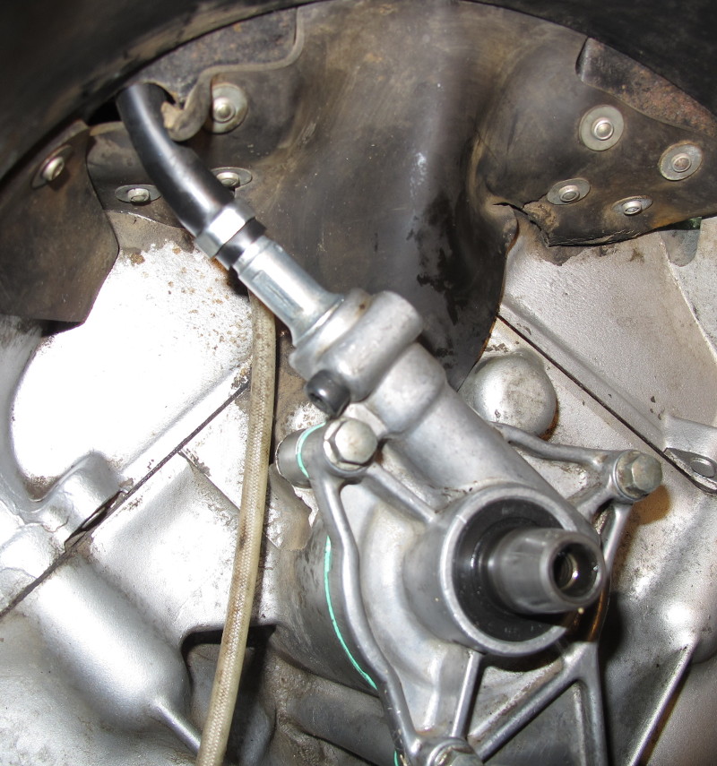
In the picture above I’ve already removed the Phillips-head screw that holds in the tach cable.  That screw was difficult to remove, especially with the fan shroud in place so, as others have suggested, I’m replacing it with an M5x20 cap-head screw.

With the camshaft holder removed, it’s easy to see one of the cams and lifters.  The screw gear drives the tachometer.

Here are the new parts.  The two o-rings are for the fork caps.
The new fan looks exactly like the old one — minus the cracks.

One of the things I discovered after removing the camshaft holder was that there was an o-ring seal that needed to be replaced.  This seal isn’t easy to find in the fiche.  I didn’t even know it was there before I pulled the camshaft holder. Fortunately the local Honda dealer had the part in stock.

I was able to remove the camshaft seal from the holder with my fingers.  It came out with very little effort.  The new seal went in just as easily.  The seal could have been easily replaced without pulling the camshaft holder — if that’s all that’s required.  Here’s the old seal and the new gasket.

Reinstalling the camshaft holder required turning the crankshaft until the pressure on the camshaft was such that the shaft was centered.  This was easily done by removing the cover near the oil filter and slowly turning the crankshaft bolt clockwise until the camshaft holder could be pushed in.  After sliding the holder most of the way in, I continued to spin the crankshaft to allow the tachometer gears to mesh as I fully seated the holder.

With the camshaft holder installed, I then installed the new tachometer cable and used a cap-head screw to hold the cable in place.  I then installed the fan and re-installed the radiator. I used blue Loctite on the holder bolts, tachometer cable keeper screw, and on the fan bolt.