
Has your temperature gauge stopped working, or does it work intermittently like mine used to? Assuming all of the wiring is in good shape, the sender hasn’t failed, and the gauge hasn’t burned out, then you need to replace your voltage regulator.
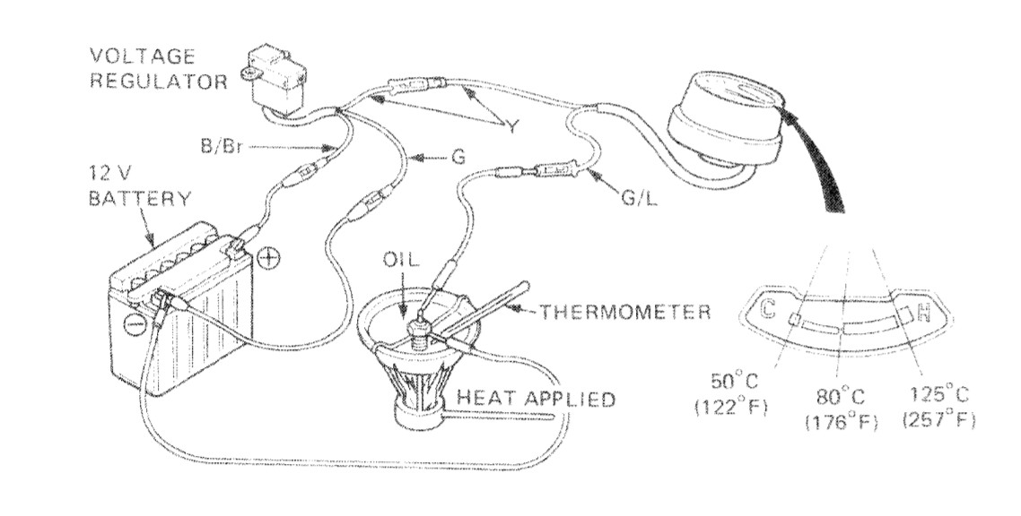
It’s easy to check everything from inside the headlight bucket. While the regulator is hanging under the gauges, the connectors are in the headlight bucket. To test the regulator, remove the headlight and with the ignition turned on, check the voltage on the yellow wire at the junction between the the regulator and the temperature gauge. It should be 7.0V, or very close to it.
If the regulator is working then check the sensor and wiring. With the ignition off, disconnect the (blue-green, G/L) gauge wire and check the resistance between the wire end going to the temperature sensor and ground. It should have some resistance, probably 1kΩ if the bike is cold. If the resistance is very high, or open, then you have a bad sensor, a bad connection at the sensor, or a bad connection in the wire near the sensor. The wire at the sensor is only a few inches long; there’s another connection just behind the air deflector on top of the engine. This wire junction is easy to access with the tank removed.
If the sender and associated wiring check out fine, then the only thing left to check is the gauge. Measure the resistance between the two gauge wires with at least one wire disconnected. You should observe a resistance of approximately 50Ω. You can also check that the gauge moves using a power supply, or a couple of AA batteries in series (see table below). Just don’t put apply more than 5-6 volts.
As I write this the OEM Honda part costs $53 plus shipping. Normally I would buy the Honda part but, besides being ridiculously expensive for what it is, electronic parts degrade over time, even when not in use, and the OEM parts have probably been sitting on a shelf for a few decades.
The voltage regulator reduces the bike’s 12-14.3V supply to a stable 7V which is applied to the temperature gauge via a yellow wire. The gauge is in series with the sender unit to ground. The 7V regulator ensures that the gauge reading doesn’t fluctuate with voltage changes in the 12V supply (e.g. loads, battery condition, RPM/charging).
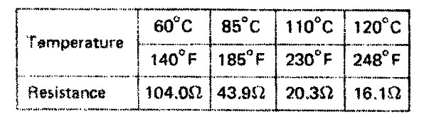
 The sender unit resistance varies with temperature as shown in this table.
 Assuming for the moment that the gauge has no resistance, the maximum current that the 7V regulator would have to supply would be 7V/16Ω or 0.43A. However, the gauge does have resistance; I measured it to be 49Ω when the gauge was cold and there wasn’t any significant current flowing through the gauge.
To better understand the gauge properties I made a series of current measurements through just the gauge while adjusting the voltage across it. Here are the results:
| Voltage(V) | Current(mA) | Resistance(Ω) | Gauge Position |
| 0 | 0 | 49 (measured) | Lowest Position |
| 2.0 | 41.4 | 82.8 | Bottom of Scale (122° F) |
| 2.5 | 52 | 130 | |
| 3.0 | 62.1 | 186 | |
| 3.5 | 72.5 | 253 | |
| 4.0 | 82.2 | 328 | Normal (176° F) |
| 4.5 | 101.9 | 458 | |
| 5.5 | 112.2 | 617 | Top of Normal (256° degF) |
The gauge moves the needle through the thermal expansion and contraction of a resistive element. As expected, the resistance of that element increases with its internal temperature. From the table we can see that, unless there’s a short in the wiring, the 7V regulator shouldn’t be required to source more than 112 mA during normal operation of the bike. It should be obvious from the two tables that as the resistance of the sender unit decreases with rising coolant temperature, the resistance of the gauge increases because of higher currents. The two changes in resistance offset each other, but not completely. The overall resistance decreases with rising coolant temperature allowing the current to increase and the gauge to indicate a higher engine temperature.
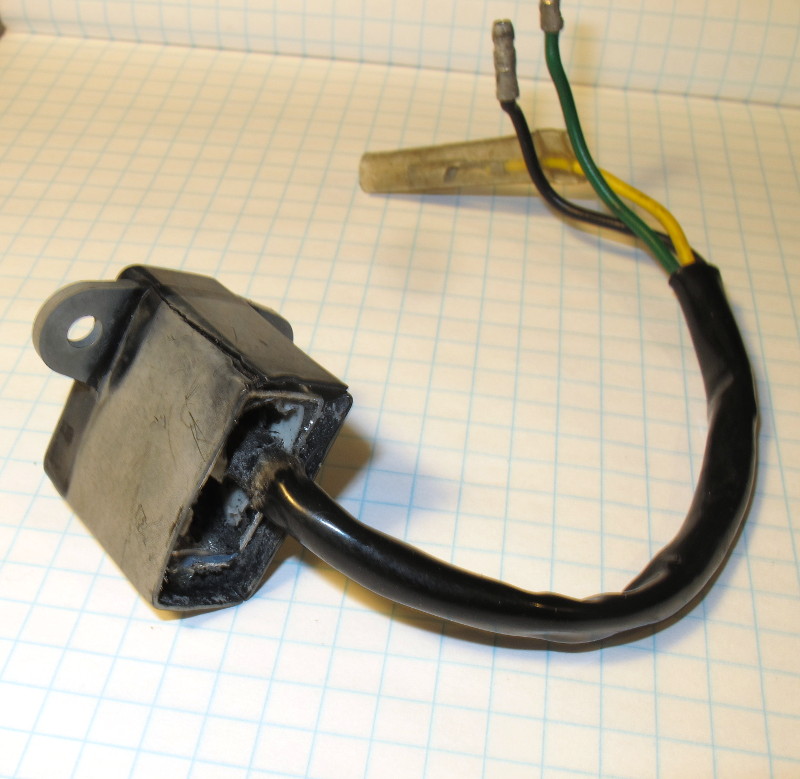
Here’s what’s left of the original regulator after an attempt to remove the potting material. Even after boiling it in hot water for several minutes I couldn’t get the case to release from the heat sink. You can see that the heat sink touches all four sides of the case.
As for replacing the 7V regulator, it is possible to build a linear regulator as others have done using a three-terminal device such as the LM7807, or a LM7805 with a 2V (green) LED. These work well, but linear regulators have one significant drawback, they’re not efficient. They lower the voltage by dissipating excess power as heat. When the bike is running the battery voltage should be near 14.3V, which means that we have to drop 7.3V across the regulator to obtain a 7V output. A 7.3V drop at 100mA is 0.73W of power that has to be continually dissipated as heat. Buck regulators are much more efficient, usually better than 90% efficient so under the same conditions 0nly 0.073W of heat will be generated. That translates to lower device temperatures and longer component life.
Searching eBay I ran across this adjustable Mini-360 Buck Converter. On paper, at least, this part is amazing. It’s very small — only 17.2mm on the long edge — smaller than a U.S. dime (17.9mm). It’s also very inexpensive. I had 10 of them delivered to my door for $4.75! That’s $0.48 for a part that is rated for 1.8A continuous and is small enough to fit in the original potted case (or a 3D printed replica). The part also has some built-in over-current protection.
To use this part all that’s required is to: solder on some wires (green to Vin+, yellow to Vout+ and black to either negative terminal); set the voltage with the potentiometer, secure the potentiometer setting, and mount in waterproof case.

The switching frequency of this device is around 340kHz so, considering switching harmonics, there probably is some RF energy up to 3-6MHz. That’s high enough to be of some concern because I don’t want to change the electrical performance of the part when I bed it in epoxy. However, with the part costing less that 50 cents I think I’ll just bed the part in some 2-part Harbor Freight epoxy that I have on hand and see what happens. Potting epoxies formulated for electronics are way too expensive for this project!
As for heat dissipation, epoxy has about 10x the thermal conductivity of still air, so if the part will run at 1.8A without a heat sink, heat should theoretically not be a problem. Still, I am a bit concerned. As a test I ran the unmounted converter with a 14V input and a 7V, 240mA output using a small incandescent light bulb as a load. Under those modest conditions the IC on the converter was too hot to touch for more than a few seconds; I expected it to be cool to the touch. Perhaps it’s more efficient at higher loads.
Here’s the 3D printed case and the regulator with the wires attached. The wire gauge I used was too large for the holes on the PCB, so I soldered some pins to the board and then soldered the wires to the pins. Post a comment if you’d like for me to send you the STL file for the case.

The new regulator is assembled and ready to install in the bike. I put two-part epoxy in the case, mixed it in place, and then inserted the board. After giving the epoxy time to cure, I powered up the converter and tested the voltage. The voltage output remained right where I set it at 7.01V, with or without a load. That’s good as it appears that the operation of the device hasn’t been degraded by the epoxy.

The new regulator hangs perfectly in the original rubber mount under the speedometer. Everything works too!
