Rebuilding the Front Forks

Mileage: 29,404

Maintenance:

  • Rebuilt front forks replacing:
    • Dust caps
    • Fork Seals
    • Fork-tube bushings
    • All air line o-rings
    • Fork oil:  210cc ATF
  • Torqued 14mm lower pinch bolts to 25 ft-lb.
  • Torqued 10mm upper pinch bolts to 11 ft-lb
  • Torqued 6mm socket cap bolt to 11 ft-lb

I recently discovered a few drops of oil on the floor under the left front fork.  I couldn’t tell if it was fork oil, or brake fluid, but the fork was very wet above the dust cap, so that’s where I started.  I’ve purchased parts to rebuild the brake caliper should that also be required.

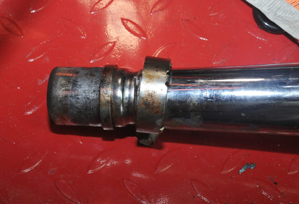
Upon closer inspection I discovered that the left-fork dust cap was cracked. Even though the forks were still holding air pressure reasonably well, given the damp tube and cracked rubber I decided it was time to rebuild the forks.

The fork oil was dirty, but not alarmingly so.  This is the left fork.  The oil in the right fork was a little cleaner.  There are no signs of water contamination, even though the cracked fork seal had allowed a bit of water to get into the slider.  Here’s the disassembled left fork before cleaning.  As always, you can click on the pictures for a larger image.  On both forks I cleaned out a small amount of black crud in the bottom of both the sliders and the pistons.

As you can see from the picture, the main spring is progressive, or at least wound with two pitches.  In the diagram below, there is a washer between the two springs.  What looks like another washer above the short spring is actually the o-ring for the cap bolt.

Fork tube bushing (bottom) and Slider bushing. The fork tube bushing is fixed in a groove around the bottom of the fork tube.  It  wears on its outside surface against the inside of the slider. The slider bushing sits below the seal at the top of the slider tube.  It wears on the inside as it slides along the fork tube.

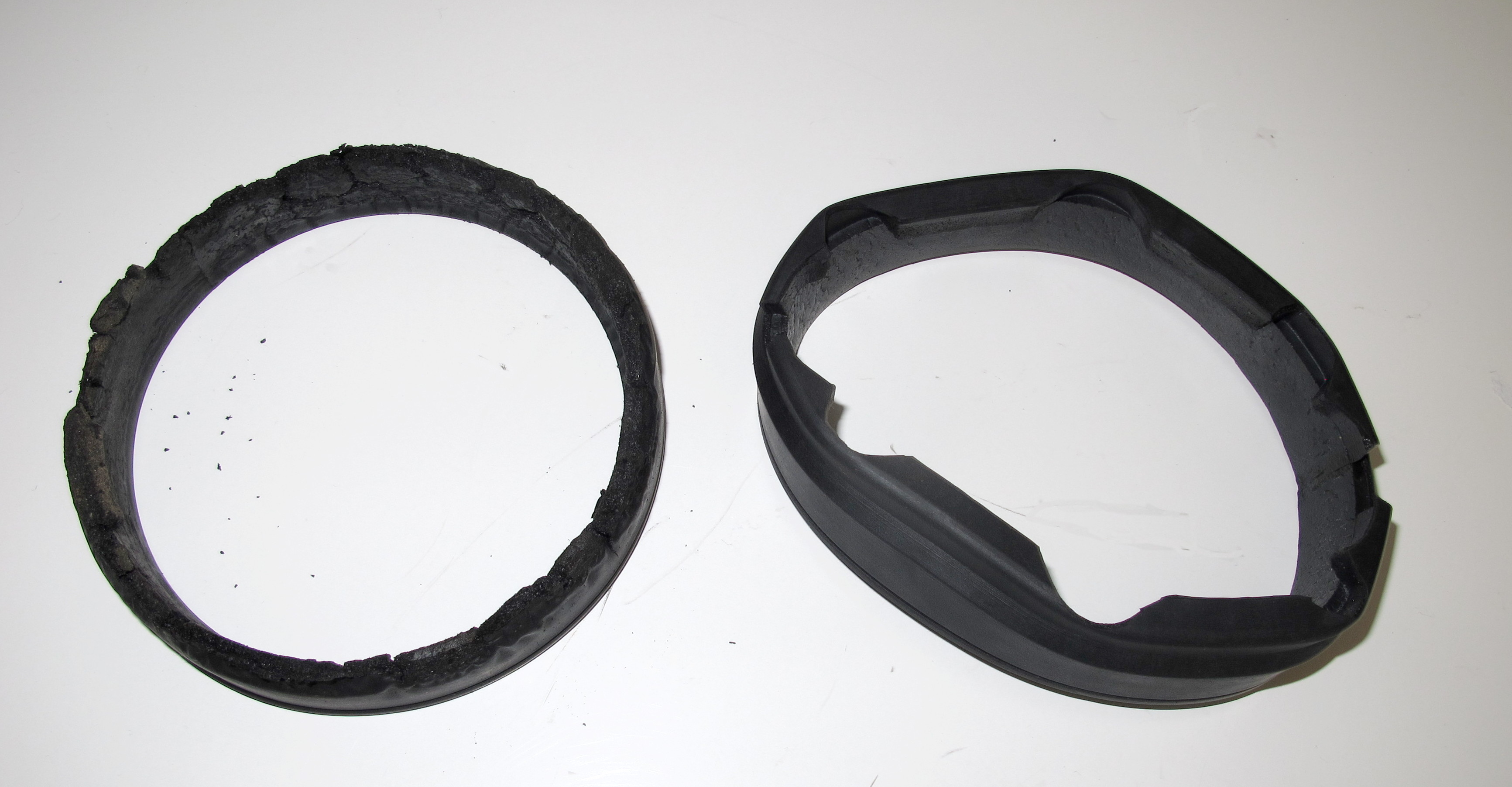
The left fork-tube bushing was about 60% worn, that is copper was showing on more than half of the exterior.  The right fork-tube bushing was closer the the 75% wear limit, so both were replaced.

Here’s the left fork-tube bushing next to its replacement.  On fork-tube bushings the (black) Teflon is on the outer surface.

The slider bushings and back-up rings showed no signs of wear on either fork.  On the slider bushings the Teflon is on the inner surface.  Other than the disassembled fork picture above, I didn’t take pictures of the white piston rings, but they were also in good shape, though the right-side ring showed a bit of yellow discoloration.  These should probably be replaced next time the forks are apart.

I used the old seals and a length of PVC pipe to drive the new seals in.    With the old seal on top of the new seal, the new seal will be in the correct position when the old seal is almost flush with the top of the slider (without the backup plate and circlip).  It was much harder than expected to seat the new seals.  However, once seated, the old driver seal is easily removed, though you may need to use a pick to pull it out far enough to grab it with a fingernail.

The manual specifies 210ml of ATF as the fork oil in each fork.  I measured the oil using a baby bottle I picked up at the local dollar store.  Baby bottles are just the right size and handily come with volume markings.  I added a line to make it easier to see.

These are the dust caps, seals, and o-rings that I installed.  The only part that I didn’t replace that I should have was the o-ring that fits around the cap bolt.  Fortunately those parts can be easily replaced without removing the forks — if needed.  The small o-rings were installed on both ends of the hose that connects the forks, and on the Schrader fill valve on the right fork.

Up Next:  With the forks done, and while the front wheel and fender are off the bike, I’m going to remove the radiator, and possibly the fan so that I can install the new tachometer cable.

Success: First long road trip

Ending mileage: 29,390

Camping near Grand Coulee Dam

While this is primarily a maintenance blog I think it’s OK to share how well this bike did on it’s first serious road trip, an overnighter covering more than 500 miles.  This bike, while being the runt of the litter, performed very well with only a few minor mechanical issues.

  • The clutch lever bolt backed out because there wasn’t a backing nut. Fortunately another rider had a locking nut that I could use.
  • The speedometer cable came loose at the instrument because I had failed to tighten it enough when I replaced the rubber surrounds.
  • After two days of riding, the rear shock pressure had bled down a bit.  I started the trip at 40 psi,  I was down to 30 psi at the start of day two.  I probably should have started at 50-60 psi because of all of the gear, and I’m not a small guy.  70 psi is the max.

We started out with six bikes, but two of the riders dropped out when a 2006 Triumph had a starter failure and then lost it’s little computerized mind.  This 36 year old bike was the oldest in the group by far.  The next oldest was the ’96 BMW, 15 years newer.

Even loaded down with camping gear I was able to keep up with the other riders except in one mountain pass where, at 4500 feet, power was lacking and I couldn’t keep up with the next larger bike, a fuel-injected 650.  There I fell behind a bit because I didn’t have enough zoom left to safely pass some large RV’s while simultaneously climbing up a steep grade.

The National Cycle fairing performed very well.  I have it tilted back to where there’s no pressure on my chest, but my helmet is riding in smooth air.  There wasn’t any serious buffeting at any of the speeds we were traveling, but I did have to clear my helmet visor of bugs several times.

The bike was very comfortable;  I really wasn’t sore after two days of riding.  The Cramp-buster helped prevent a sore wrist.  A throttle lock would have been useless on this trip because of all of the twisty roads we were on.

I usually managed something close to 50 mpg for the trip.  Not bad given that I had to use a little more right-hand wrist action to keep up with the larger bikes.


Saddlebags, Truck-bed liner and Tail Light Extenders

The first bag is finished.  While I’m not trying to turn this bike into an Interstate model,  there are will be times when saddlebags are helpful.  I don’t know if they ever made them in the Cosmo Black, the color of my bike.  I’ve never seen any for sale.

I picked up a pair of saddlebags on eBay which looked like they might have been black — they weren’t — but which were so beat up it didn’t matter.   The cases came without keys, but my local lock smith was able to quickly make keys using the code stamped on the locks.  Unfortunately he couldn’t do what I really wanted which was to re-key the locks to my bikes ignition key. (Click on pictures to enlarge)

Here’s the left bag before painting.  It doesn’t have as many scratches as the right bag, which is on the left in the picture above, but it had some cracks that needed repairing.

If you’re interested, I’ve created a separate page describing how I refurbished these bags.

When I bought the bike, I mistakenly thought it was ready for bags.  It had crash bars and the latch tab at the passenger foot pegs.  However, the bike required a couple of more modifications before the bags could be mounted.

Note: This picture was taken right after I bought the bike. The bike looks much better now!

The first item is the tail light extender shown in the next picture.

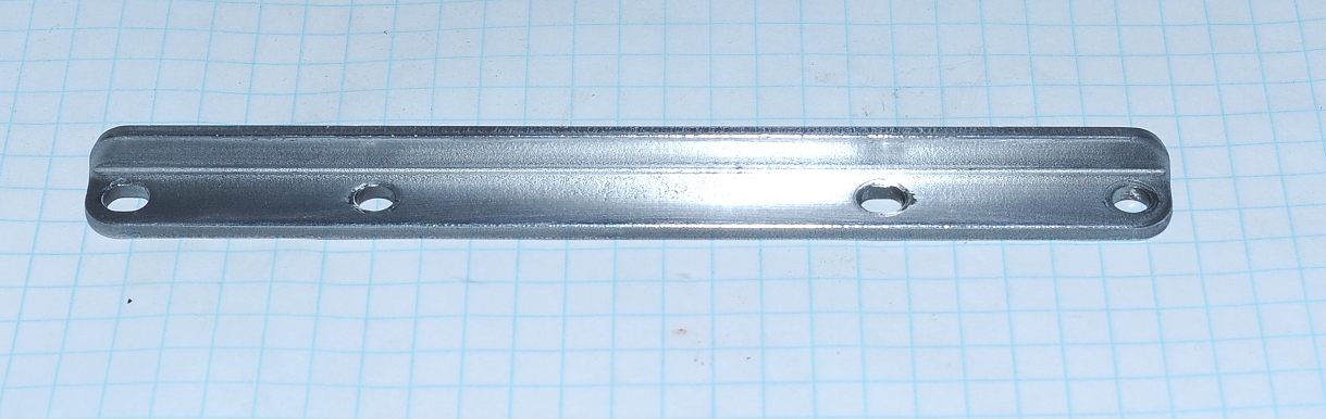
The extender mounts as shown with two 6×45 bolts and two 6×16 bolts.  Before adding the bracket, the tail lights were mounted to flat tabs at the location now occupied by a fender washer and bolt.  Unlike the tabs on the extender which are welded on, these tabs have a bolt and nut, allowing them to be removed. The second modification that needed to be performed was to lengthen the tail light wires.  For that, I simply cut the wires and soldered in some extra wire.  That way I kept the original connectors.  I used heat shrink to cover both the solder joints and the entire length of wiring.

The mounting system on these bags seems overly complex, and heavy.  If you’ve never used one of these,  the bar with the “Press” button that looks like a seat belt fastener swings forward on a hinge and locks into place with the bit of hardware on the lower, left of the bag pictured below.  When mounted it hooks into a tab on the passenger foot peg.  The chrome mount in the center of the case (which is now black) fits over the bar that runs along the seat.  The plastic mount on the far right fits over the rubber bumper on the tail light extender, and the rubber encased tab on the lower right of the case slips into the rectangular box on the lower part of the extender.  The helmet lock arm then folds down over the plastic tab just to the right of center, preventing the bag from falling off, or being removed.

If you don’t have the extenders on your bike and you want to fit factory bags, find some.  There’s really no easy way to mount factory bags without them.

Picture taken

Rear Suspension Service: This must be what a new bike feels like!

InMileage: 28,400

Today’s Maintenance:

  • Rear Suspension Service
    • Removed and Re-installed Pro-Link suspension
    • Cleaned and then greased all pivot bolts, bushings and caps with hi-moly grease
      • Note:  Did not service pivot bolt at top of shock
    • Removed and re-installed the mufflers
      • Coated with red-copper anti-seize

The rear suspension began squeaking after the last long ride so I performed the service described here.  Not only did the squeak go away after servicing the Pro-Link suspension, the bike feels way smoother to ride.  If you have a GL500 and haven’t done this service, do it!  It’s not that hard, or time consuming (depending on your exhaust).

Greasing the suspension is not listed as a regular service item, but it’s not surprising on a 36 year old bike to expect that some of the grease might not be as effective as it was when new.   In this case, there wasn’t any grease left.

In the next picture, going from left to right, the two rear pivot bolts were dry, but otherwise in good shape.  The shock bolt looked new even though it too was dry.  The shock attaches to the upper tabs of the left link. As you can see, the pivot bolt that ties the two links together has some corrosion, as does the front pivot bolt (which was partially cleaned before taking this photo). The corrosions is not as bad as it looks.  There was some minor pitting on both the bolts and the bushings, but not so much as to cause concern.

I cleaned up the bolts and bushings using a mixture of ATF and acetone — sliding and spinning the bolts inside the bushings.  I then followed up with some brake cleaner to degrease everything.  The bolts I further cleaned up with a wire brushing and Scotchbrite pad.

The six caps were removed and cleaned as well.  As I put things back together I used an acid brush to coat the bushings and caps with a high-moly content paste grease.  I also coated the pivot bolts as I re-installed them.

Service hint:  With the bike on the center stand, the shock is supporting the rear wheel.  If you support the wheel, or lift it with a prybar or large screw driver, you can take the pressure off of the shock pivot bolt making it much easier to extract.  You’ll need to do this anyway when you go to put everything back together.

The service manual seemed to imply that you only needed to remove the right muffler to service the rear suspension.  Not true.  The front pivot bolt can’t be removed with the “power box” in place.  Also getting to one of the nuts on the left side for proper torquing required removing the left muffler as well.  In the end I had to remove the exhaust rings so that I could slide the headers and power box forward and down a bit.   In hindsight, it might have been possible to remove the entire exhaust system as one unit, eliminating the need to separate the mufflers from the power box.

The mufflers were a pain to remove.  After struggling with the right side for some time I finally found a strategy the worked.  Here’s the recipe;

  1. Use a large screw driver to carefully pry the tabs on the power box away from the muffler just enough to help break the bonds.
  2. In a well ventilated space, use your favorite penetrating oil, or create a 50/50 mix of ATF and acetone in a paper cup, mix well and then poor it over the the tabs.  You don’t need to mix up very much.  Wait for a while, at least 15 minutes.  Longer is better.
  3. Place a wet shop rag over the muffler as close to the power box as possible.  This will help keep the muffler cool.
  4. Use a heat gun, not an open flame, to heat the power box in front of the tabs.
  5. After a few minutes of heating the power box, slide the shop rag back and hit the muffler with cold spray (I used a can of Dust-Off turned upside down)
  6. Pry the back end of the muffler up and down as well as out and in while banging on the mounting bracket with a rubber mallet (where the passenger foot peg is located).   This will drive the muffler out while the pushing and pulling will help break the bonds.

Here are a couple of pictures to show you what you’re up against. The muffler slides into a soft metal sealing ring which slides into the power box.  This is the right muffler.  The ring came out with the muffler on this side.  These pictures show the mufflers just the way they came out.  Nice and clean, but still hard to extract.

On the left side, the sealing ring stayed in the power box.

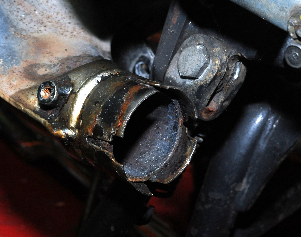
Here’s the sealing ring for the left muffler.  I didn’t try to remove it from the power box.When I re-installed the mufflers I coated them with red-copper anti-seize.  I also put a dab of the anti-seize on the screws that hold the chrome power box covers.

New Gauge Rubber and Speedometer cable

Mileage: 28,125

Today’s Maintenance:

  • Installed new instrument rubber surrounds
  • Installed new speedometer cable

After a lubricating the tach cable, it was much better, but still a bit twitchy. The tach and speedo cables are both available, and not too expensive, so I ordered both.  I also ordered the rubber bushings that the instruments slide into.  As discussed in a previous post, those were in pretty bad shape.

The parts arrived today, so I installed everything except the tach cable.  It turns out that to replace it I have to pull the radiator, and probably the fan, so we’ll just see how well the old cable continues to work.

The speedometer cable was easy to replace.  The old one is in very good shape, no rust on the inner cable, so  I’ll keep that one as a spare.

The old instrument rubber I didn’t keep.  As you can see in the picture below, there’s not much left of the old part (left).  The new part is on the right.  What’s interesting is that the rubber that was exposed around the top of the instrument, wasn’t too bad,  it was the stuff at the bottom that was cracked and as hard as rock.

With the new surrounds, the instruments are no longer loose.  They’ll probably last longer too as the new surrounds better absorb the vibrations.

First Serious Test Ride

Ending Mileage: 28,079

With new tires,and the maintenance and repairs 99% complete it was time to give the bike a longer test run to discover any remaining issues, and to start breaking in the tires.

The 70 mile trip primarily consisted of the following:

  • Rush hour traffic (stopped for about 10 minutes trying to get onto a highway) on the way out
  • 40-50 MPH twisty back roads on the way out
  • 60 and 70 MPH Freeway driving on the way back.
  • Some 25-35 MPH city driving on both ends

The bike did great!   The only problem that I encountered was a lack of lubrication in the speedometer and tachometer cables.  The tach, especially, was bouncing around above 5000 RPM.

While I was idling in stopped traffic the bike did slowly warm almost to the top of the normal range, but it never overheated.  If I were to do much of this kind of riding I think I’d upgrade to an electric fan.  When the bike was moving the temp gauge pretty much stayed at the transition between the thin and wide white bars.   In other words, right where it should be.

Curious about fuel economy I fueled up near the start of this trip, and again at the end.  I burned about 1.3 gallons over 67 miles, or 51 MPG.  Not bad!


New Tires and Grips

Mileage: 27,992

Today’s Maintenance:

  • Installed and Balanced New Front/Rear Tires:  Shinko 712’s
    • Front:  100/90H-19, Inflated to 28 psi
    • Rear: 130/90H-16, Inflated to 36 psi
  • Replaced Brake Stopper Arm Cotter pin
  • Adjusted rear brake
  • Replaced Grips:  ProGrip 714’s

Today the bike got new tires,  Shinko 712’s. The Shinko’s, while  inexpensive, come highly rated.  Shinko bought the motorcycle tire division from Yokohama.

Changing tires is a pain.  I’d like to think that it’s because the tires are old and stiff — not me.  On the rear I managed to get one side off, but for the other side I finally ended up cutting part of the outer tire away with a Sawzall so that I could get at the bead wires with a bolt cutter.

I used the “2×4 method” to break the tires.  That was easy.  For my pivot point I just C-clamped a 2′ length of 2×4 to a 4×6 post supporting my deck.

After getting the new tires on, which wasn’t too bad, I couldn’t get the front tire bead to seal and seat. Nothing worked.  I tried removing the stem core, a shorter air hose, a strap around the tire, thicker soap, bouncing the tire, zip ties and various combinations of the above.

Unwilling to use explosives to seat a motorcycle tire, I took the wheel to a custom tire shop.  The shop’s larger air compressor didn’t work either, but they had a “Cheatah”, or bead seater.  You can buy these things for $50 on eBay, delivered.  You can also build one using a propane, or similar tank.   All they are is a 5-gallon air tank with a 1.5-2″ valve and pipe.  You fill the tank and then quickly open the valve while filling the tire with air.  Fast and easy.  It’s too bad I couldn’t justify buying one of these, it turns out they can also be turned into potato guns.  The tire shop only charged me $10.

After balancing the tires, I installed them on the bike.  I discovered that  Shinko rear is a bit wider than the Metzler it replaces.  I know this because I had to deflate the tire to get it past the final drive.  I didn’t have to do that with the Metzler.

Balancing the rear tire

Before mounting the tires I put the wheels on the balancer to find and mark the rim’s heavy spot.  Unfortunately, after mounting the tire on the front wheel I discovered a stick-on weight that I had missed;  I had removed the spline weights.  Not wanting to remove the tire, I removed the errant weight and just aligned the tire’s light mark with the stem, the way they do at the dealer.

On the rear, the heavy side was almost on the opposite side of the tire from the stem, so that’s where I aligned the tire’s light mark. The front wheel took 20 grams to balance, 15 grams for the rear.  If I had aligned the mark on the tire with the rear stem, it would have taken a lot more weight to balance.

I couldn’t re-use the weights that clip over the wheel spline — too heavy.  At some point, for aesthetics, I may replace the silver weights I installed with black ones.  All I had were silver.

When I ordered the tires, I also ordered new grips for $10.  The grips that were on the bike were ProGrip 714’s.  I like these gel grips, but the left one was damaged on the end.  I used compressed air to blow the old grips off, and again to blow the new grips on, though I guess I’m technically pushing them on as the air is trying to blow them off.  Very fast and easy, no soap, alcohol or hairspray.


Carburetors Take Two

Mileage: 27,982

Today’s Maintenance:

  • Disassemble and clean carburetors
  • Zinc plate straps, strap screws, and cable bracket
  • Zinc plated seat bolts, washers and spacers
  • Replace accelerator pump
  • Replace bowl gaskets
  • Lubricated choke and throttle cables
  • Adjusted idle mixture
  • Adjusted idle speed
  • Slightly repositioned master brake cylinder to be more upright

When I first got the bike it wasn’t running.  The problem was clogged jets.  As I didn’t have rebuild kits at the time, I just cleaned out the jets and bowls and put the bike back together.

With rebuild kits in hand I removed the carbs again.  This time I separated the carbs so that I could get to all of the parts and give the carbs a more thorough inspection and cleaning.

I didn’t have replacement throttle plate screws, and wasn’t even sure the kit contained throttle-shaft seals, so I left those alone.  The thottle shafts seem pretty tight fitting.  The choke shafts had a fair amount of play in them, but air getting in past the choke shafts shouldn’t affect mixture.

One of the air cut-off valves was missing a very small seal.  This is another part that wasn’t in the kit.  However, as it turns out, the very small o-ring seal is the same diameter as the seal and washer that goes around the idle mixture screw, but much thicker.  I had extra idle mixture screw seals, but they weren’t thick enough for a good seal.  To get around the problem I used an idle mixture screw washer under the seal to push it up high enough that the cover would seal against it.  The cut-off valves were in great shape.

Note for future reference: The air cut-off valve with the hacked seal is the one that’s accessible on the left side of the bike.  If a proper seal can be obtained, it can be installed without removing anything from the bike.

The previous owner told me that the carbs had been rebuilt three years ago.  That seems to be the case as I ended up not replacing anything except the bowl seals, and one of the floats which I accidentally broke.   Unfortunately, the kits didn’t include new rubber plugs.  As you can see in these pictures, the rubber isn’t in good condition.  Those parts aren’t available from Honda, but I think there are after market parts on eBay.  They should be replaced because bits could fall off and clog a jet.

The new accelerator pump is on the bowl on the left in this picture.  The new bowl seals are also in place.The carbs are ready to go back in the bike.  Here you can see the re-plated front strap and cable bracket.  While I had everything apart I gave the tops a quick polish as well.  It’s too bad you can’t see much of the carbs when they’re on the bike.  They look pretty good!After lubricating the cables, the throttle was still sticky.  It turns out that I had routed the cables under the frame rather than over, as shown in this picture, which was taken right after I bought the bike.  I removed the carbs — again — and routed the cables over the frame.  Works great now.  It’s psychological, I know, but with less friction in the throttle cables the bike feels quicker.  Who knows, with cleaner carbs the bike might have a bit more power.

Throttle and choke cables route over the frame (the bike was pretty dirty when I bought it!)

After installing the carburetors I warmed the bike up and started dialing in the mixture.  I used the RPM drop method to get close and then tweaked a bit until the idle was smooth, and had good throttle response.

The bike is running really good now, at least at in-town speeds.  After I borrow, or make a tool to balance the carbs, I’ll do that and re-tweak the idle mixture.

While working on the throttle cables, I decided that the master cylinder should be more upright.  So I repositioned it, and added more DOT4 fluid.

Zinc Plating Carb Parts

The two straps that hold the carbs together on this old bike had some corrosion on them. Since I managed to drop and break one of the floats  while rebuilding the carbs, I had some time to consider plating those parts while I wait for the replacement float to arrive.  After researching DIY zinc plating  I decided it didn’t look that hard.  It wasn’t!

I’m so pleased with the results that I’m now looking around and asking “What else can I plate?”.

On the carbs I plated the front and rear straps, and the cable clamp bracket.

I’ve created a separate page that describes how to do this.

This was cleaned and polished less than a month ago. The rust has already returned.
Zinc Plated and Polished. I don’t expect it to rust again for a long time